Implementing a Storage Area Network Prototype
Objective
This project was the result of projects on the design and simulation of a storage system for the Department to Engineering Science (DES). These projects suggested that a core-edge SAN might provide improved performance and reliability over the existing storage system. NDSG received funding to build a prototype storage system to compare to the models developed.Initial Core-Edge SAN Implementation
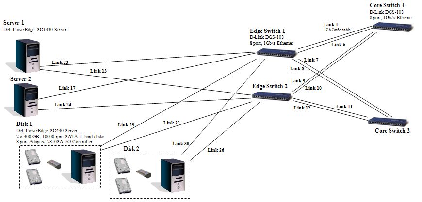
The network we set out to build was the result of design and simulation work on the DES storage system. The final design of the network is shown below: (For a full size image see the design project.)
As a first step in implementing this design we are building an experimental network consisting only of the New Servers and the Disks with a smaller-core-edge network:
(For a full size image see the design project.)
As a first step in implementing this design we are building an experimental network consisting only of the New Servers and the Disks with a smaller-core-edge network:
Purchasing the Network
We purchased the “kit” for building this network from PB Technologies. While they did not have the exact components of the original network, they supplied us with the equivalent network for less cost. Below is a summary of the New Servers, Disks and Link from PB Tech:| New Server 1 | HP Proliant + NIC card |
|---|---|
| New Server 2 | HP Proliant + NIC card |
| Disk 1 | Tower, motherboard, processor, 2 x 1TB SATA-2 drives |
| Disk 2 | Tower, motherboard, processor, 2 x 1TB SATA-2 drives |
| Links | Cat 6e cable |
| Switches | 4 x 3Com OfficeConnect Gigabit Switch 8 |
Storage System Architecture
We wanted to use iSCSI to present the Disks to the New Servers, mdadm to multipath and RAID the storage and Red Hat Cluster Suite with GFS to allow access to the storage. A diagram of our proposed architecture is shown below: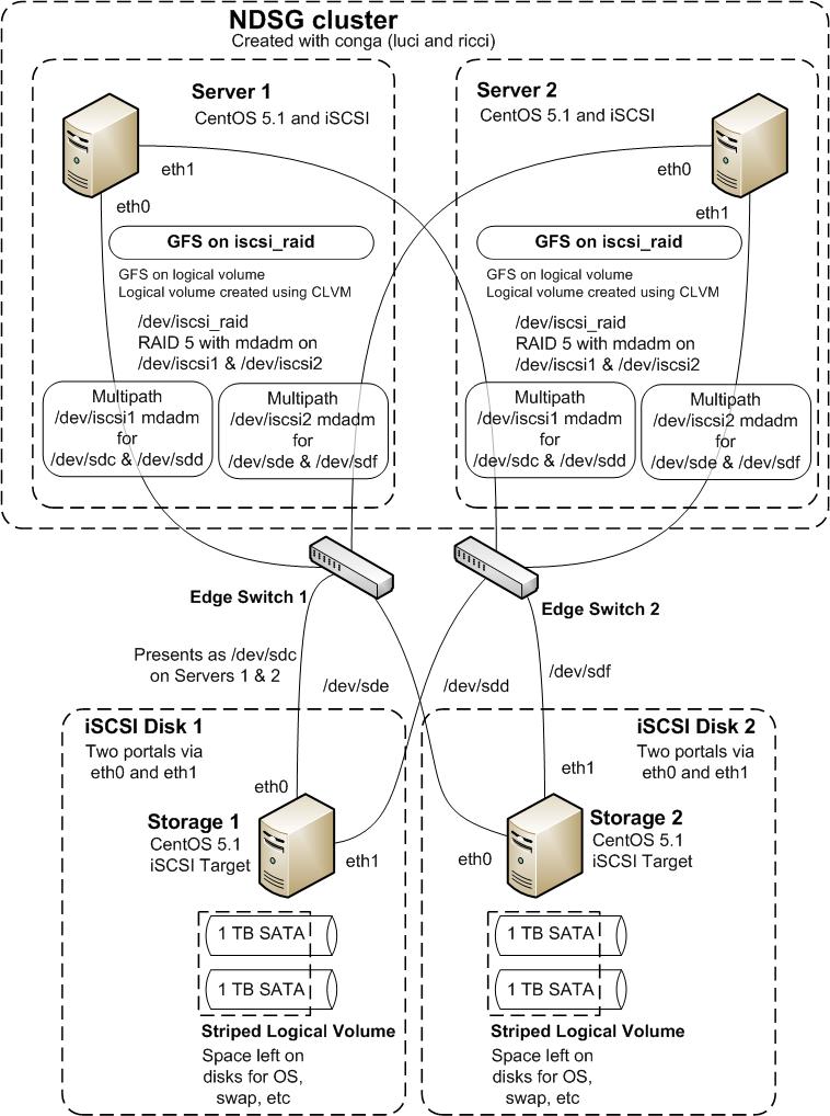
Configuring the Components
The first task was to add the extra NIC to the HP Servers to provide 2 ports. This involved opening the case and pushing the card into one of the extra NIC slots. The HP Proliant servers came with the ability to install Windows Server 2003. However, given that we wanted to cluster the servers and use iSCSI we opted to use CentOS 5 on these servers instead. Using 6 installation CDs we successfully installed CentOS on both servers (these servers did not have a DVD drive). The next task was to build the storage boxes, we had to assemble these PCs by hand following step-by-step instructions posted on the internet. We were successful in building the boxes (they passed a check by our IT staff). We had to get some extra SATA cables for the disk drives as the DVD for these boxes also used SATA. Also, we did not get extra NIC cards for these boxes in our initial purchase, so we had to obtain and install these. We also installed CentOS in these boxes, but encountered a problem with ACPI. This was overcome during installation by installing usinglinux acpi=offInitially we chose to install Virtualisation, Clustering and Storage Clustering (along with the Desktop and Server modules), but this caused a problem with the CentOS boot (xen):
irq #9 ata1: COMRESET (errno = -16)Fortunately the base kernel was there and working, so I edited
grub.conf to set this as the default. This could also have been solved by a complete reinstall.
We ran
yum update -yon all the boxes to make sure they were up to date.
Building the Network
Building the network was simple (as it is a small configuration). We discovered we needed crossover cables for the inter-switch links (ISLs). We also discovered that one of the added NIC cards was not pushed all the way into its slot and fixed that. One of our IT staff set up the network and also allowed all the boxes to connect to the internet via Server 1. He used the correctiptables commands and put the right settings in the Network Administration dialog to set this up.
The map between the ports and the IP addresses is as follows: - Server 1 eth0 is connected to the internet with IP address xxx.xxx.xxx.155 and to the network with IP address 192.168.100.5. eth1 is assigned IP address 192.168.100.1.
- Server 2 eth0 and eth1 are 192.168.100.2 and 192.168.100.3 respectively.
- Disk 1 eth0 and eth1 are 192.168.100.6 and 192.168.100.7 respectively.
- Disk 2 eth0 and eth1 are 192.168.100.11 and 192.168.100.13 respectively.
Configuring the Storage Devices
First, we need to install iSCSI Target on the storage boxes. We downloaded the latest version of iSCSI Target from SourceForge. We also neededgcc and open-ssl to install iSCSI Target. We installed the necessary packages as follows
yum install gcc
yum install openssl-devel
yum install kernel-devel
Then, in the directory where we saved the iSCSI Target tarball (iscsitarget-0.4.16.tar.gz in our case) we ran the following commands
make
make install
iSCSI Target was then installed! We didn't need to edit
initiators.allow as there were only our servers on the network. However, to keep you target secure you may want to edit this.
Next, we set up the targets by editing /etc/ietd.conf:
# Edited next line
Target iqn.2008-09.nz.net.ndsg.disk1:storage1
        # Users, who can access this target. The same rules as for discovery
        # users apply here.
        # Leave them alone if you don't want to use authentication.
        #IncomingUser joe secret
        #OutgoingUser jim 12charpasswd
        # Logical Unit definition
        # You must define one logical unit at least.
        # Block devices, regular files, LVM, and RAID can be offered
        # to the initiators as a block device.
        #Lun 0 Path=/dev/sdc,Type=fileio <- removed and added next line
        Lun 0 Path=/dev/sda2,Type=fileio
        # Alias name for this target
        # Alias Test <- removed and added next line
        Alias storage1
        # various iSCSI parameters
        #MaxConnections          1 <- added next line to allow for multipathing
        MaxConnections          2
Initially we tried to add two LUNs to the target (one for each disk drive in the storage box), but we realised this was not possible. In fact, we had to reinstall with a custom partition for the storage. On sda we had - 100MB /boot
- 8GB /
- 4GB swap
- the remaining space was left for the storage
sdb entirely for the storage.
We then created a striped logical volume (using Logical Volume Management) over the storage sections of sda and sdb. Since the size of storage use on sda and sdb needed to be the same for striped LV, there was ~9.9Gb of space left on sdb.
Then we could present this single LUN as an iSCSI target.
Alternatively, we could have created files to serve as the iSCSI targets
dd bs=1G count=2000 if=/dev/zero of=/iscsi/disk1Next we started iscsi-target
service iscsi-target startand make sure it persists by adding it to
chkconfig
chkconfig --add iscsi-target
chkconfig --levels 2345 iscsi-target on
Configuring the Servers
First, we installed iSCSI on the New Servers (to act as storage controllers)yum install iscsi-initiator-utilsThen, one would normally edit
/etc/iscsi/iscsid.conf to set up usernames and passwords for iSCSI. Since this network is experimental we are not using usernames and passwords so we skipped this step.
Then we set the name of the initiator in /etc/iscsi/initiatorname.iscsi.
#InitiatorName=iqn.1994-05.com.redhat:2828cb48ea2 <- commented out here, added line below
InitiatorName=iqn.2008-09.edu.byu.et.265r.croi-01:controller1
Next, we started iSCSI
service iscsi startand made sure it persisted by adding it to
chkconfig
chkconfig --add iscsi

chkconfig --levels 2345 iscsi on
Now, we could discover the iSCSI disks.
iscsiadm -m discovery -t sendtargets -p 192.168.100.6
iscsiadm -m discovery -t sendtargets -p 192.168.100.7
iscsiadm -m discovery -t sendtargets -p 192.168.100.11
iscsiadm -m discovery -t sendtargets -p 192.168.100.13
Next, change the portals for Disk 2 to be part of portal group 2 (since they point to a different target).
iscsiadm -m node -o delete -T  Target iqn.2008-09.nz.net.ndsg.disk2:storage2
-p 192.168.100.11,1
iscsiadm -m node -o delete -T  Target iqn.2008-09.nz.net.ndsg.disk2:storage2
-p 192.168.100.13,1
iscsiadm -m node -o new -T  Target iqn.2008-09.nz.net.ndsg.disk2:storage2
-p 192.168.100.11,2
iscsiadm -m node -o new -T  Target iqn.2008-09.nz.net.ndsg.disk2:storage2
-p 192.168.100.13,2
Now, login to your iSCSI nodes
iscsiadm -m node --loginand check the disks are available (note there will be multiple copies of the same disk, e.g., sdc and sdd both point to Disk 1)
fdisk -l
Building the Storage Network
First, make a new loop device in/etc/udev/devices (to make sure it survives a reboot),
[root@server1 ~]# mknod /etc/udev/devices/iscsi2 b 9 102symbolically link it to a "regular" device
[root@server1 ~]# ln -s /etc/udev/devices/iscsi2 /dev/iscsi2and use
mdadm turn it into a multipath device
[root@server1 ~]# mdadm -C /dev/iscsi2 --auto=yes --level=multipath --raid-devices=2 /dev/sde /dev/sdf
mdadm: /dev/sde appears to contain an ext2fs file system
    size=1928724480K  mtime=Mon Apr 21 10:39:50 2008
mdadm: /dev/sdf appears to contain an ext2fs file system
    size=1928724480K  mtime=Mon Apr 21 10:39:50 2008
Continue creating array? y
mdadm: array /dev/iscsi2 started.
Once all your disks have been created as multipath devices you can gather them together into a RAID-5 array also using mdadm
mknod /etc/udev/devices/iscsi_raid b 9 100
ln -s /etc/udev/devices/iscsi_raid /dev/iscsi_raid

mdadm -C -v /dev/iscsi_raid --auto=yes -l5 -n2 /dev/iscsi1 /dev/iscsi2
mdadm: layout defaults to left-symmetric
mdadm: chunk size defaults to 64K
mdadm: /dev/iscsi1 appears to contain an ext2fs file system
    size=1932787712K  mtime=Mon Apr 21 10:22:14 2008
mdadm: /dev/iscsi2 appears to contain an ext2fs file system
    size=1928724480K  mtime=Mon Apr 21 10:39:50 2008
mdadm: size set to 1928724352K
Continue creating array? y
mdadm: array /dev/iscsi_raid started.
Now your RAID-5 disk array is complete and you can use it like regular storage. However, we will wait until we have created the storage controller cluster before creating physical volumes, volume groups, etc.
Now create a configuration file for use on any other storage controllers. Copy the output of an mdadm scan to /etc/mdadm.conf
# mdadm --examine --scan
ARRAY /dev/md102 level=multipath num-devices=2 UUID=xxx:xxx:xxx:xxx
ARRAY /dev/md101 level=multipath num-devices=2 UUID=xxx:xxx:xxx:xxx
ARRAY /dev/md100 level=raid5 num-devices=2 UUID=xxx:xxx:xxx:xxx
rename the devices to the loop device created and add the iSCSI devices, e.g.,
DEV /dev/sd[bcde] /dev/iscsi[12]
ARRAY /dev/iscsi2 level=multipath num-devices=2 UUID=xxx:xxx:xxx:xxx
ARRAY /dev/iscsi1 level=multipath num-devices=2 UUID=xxx:xxx:xxx:xxx
ARRAY /dev/iscsi_raid level=raid5 num-devices=2 UUID=xxx:xxx:xxx:xxx
Next, add the appropriate devices to the ARRAY lines
DEV /dev/sd[bcde]
ARRAY /dev/iscsi2 level=multipath num-devices=2 UUID=xxx:xxx:xxx:xxx devices=/dev/sdd,/dev/sde
ARRAY /dev/iscsi1 level=multipath num-devices=2 UUID=xxx:xxx:xxx:xxx devices=/dev/sdb,/dev/sdc
ARRAY /dev/iscsi_raid level=raid5 num-devices=2 UUID=xxx:xxx:xxx:xxx devices=/dev/iscsi1,/dev/iscsi2
and your configuration file is complete. On any extra storage controllers you need to perform all the iSCSI steps and create the loop devices, but you don't need to build the devices using
mdadm. Simply copy the mdadm.conf file to the machine, edit the drive names (e.g., sdb may represent a different drive on the new machine) and use
mdadm --assemble /dev/iscsi2etc IMPORTANT You need to make sure that the iSCSI portals are loaded in the same order on all storage controllers so that
/dev/sdb, /dev/sdc, etc are the same. We created a script to ensure this:
echo -n "Resetting iSCSI drives"
echo
NETS="100"
tpgt=1
NICS="6 7"
for nic in $NICS; do
  for net in $NETS; do
    iscsiadm -m node -T iqn.2008-09.edu.byu.et.265r.sophia$tpgt:storage$tpgt -p 192.168.$net.$nic:3260,$tpgt --logout
  done
done
tpgt=2
NICS="11 13"
for nic in $NICS; do
  for net in $NETS; do
    iscsiadm -m node -T iqn.2008-09.edu.byu.et.265r.sophia$tpgt:storage$tpgt -p 192.168.$net.$nic:3260,$tpgt --logout
  done
done

fdisk -l

# Creating iSCSI drives

echo -n "Creating iSCSI drives"
echo
NETS="100"
tpgt=1
NICS="6 7"
for nic in $NICS; do
  for net in $NETS; do
    iscsiadm -m node -T iqn.2008-09.edu.byu.et.265r.sophia$tpgt:storage$tpgt -p 192.168.$net.$nic:3260,$tpgt --login
    fdisk -l
  done
done
tpgt=2
NICS="11 13"
for nic in $NICS; do
  for net in $NETS; do
    iscsiadm -m node -T iqn.2008-09.edu.byu.et.265r.sophia$tpgt:storage$tpgt -p 192.168.$net.$nic:3260,$tpgt --login
    fdisk -l
  done
done
Building the Storage Controller Cluster
The final step is to create a storage controller cluster to create physical volumes, volume groups and a GFS on the iSCSI raid device. First, make sure that you have the Red Hat Cluster Suite installed (i.e.,cman, rgmanager, clvm). I have also installed luci and ricci so I can use the web-based management interface conga. Here is a good reference manual:
RHCS Administration
For example, you can install ricci and luci as the logical volume manager for clusters as follows:
yum install ricci
yum install luci
yum install lvm2-cluster
You must make sure the correct IP ports are enabled so that the cluster can communicate
- Cluster Manager (
cman)
iptables -A INPUT -i ~~<ip_address>~~ -m multiport -m state --state NEW -p udp -s ~~<subnet_mask>~~ -d ~~<subnet_mask>~~ --dports 5404,5405 -j ACCEPT
- Cluster Node and luci Server (
luci)
iptables -A INPUT -i ~~<ip_address>~~ -m multiport -p tcp -s ~~<subnet_mask>~~ -d ~~<subnet_mask>~~ --dports 8084 -j ACCEPT
- Cluster Node and luci Server (
ricci)
iptables -A INPUT -i ~~<ip_address>~~ -m multiport -m state --state NEW -p tcp -s ~~<subnet_mask>~~ -d ~~<subnet_mask>~~ --dports 11111 -j ACCEPT
- Cluster Node and luci Server (
modclusred)
iptables -A INPUT -i ~~<ip_address>~~ -m multiport -m state --state NEW -p tcp -s ~~<subnet_mask>~~ -d ~~<subnet_mask>~~ --dports 16851 -j ACCEPT
- Cluster Node and luci Server (
dlm)
iptables -A INPUT -i ~~<ip_address>~~ -m multiport -m state --state NEW -p tcp -s ~~<subnet_mask>~~ -d ~~<subnet_mask>~~ --dports 21064 -j ACCEPT
- Cluster Node and luci Server (
rgmanager)iptables -A INPUT -i ~~<ip_address>~~ -m multiport -m state --state NEW -p tcp -s ~~<subnet_mask>~~ -d ~~<subnet_mask>~~ --dports 41966,41967,41968,41969 -j ACCEPT
- Cluster Node and luci Server (
ccsd, TCP)iptables -A INPUT -i ~~<ip_address>~~ -m multiport -m state --state NEW -p tcp -s ~~<subnet_mask>~~ -d ~~<subnet_mask>~~ --dports 50006,50008,50009 -j ACCEPT
- Cluster Node and luci Server (
ccsd, UDP)iptables -A INPUT -i ~~<ip_address>~~ -m multiport -m state --state NEW -p udp -s ~~<subnet_mask>~~ -d ~~<subnet_mask>~~ --dports 50007 -j ACCEPT
IPTABLES=/sbin/iptables
CLUSTER_INTERFACES="eth0 eth1"
TCP_PORTS="41966 41967 41968 41969 50006 50008 50009 21064 16851 11111 8084 860 3260"
UDPPORTS="50007 5404 5405 6809"

echo -n "Applying iptables rules"
echo
for interface in $CLUSTER_INTERFACES; do
  for port in $TCP_PORTS; do
    $IPTABLES -I INPUT  -i $interface -p tcp -m tcp --sport $port -j ACCEPT
    $IPTABLES -I INPUT  -i $interface -p tcp -m tcp --dport $port -j ACCEPT
    $IPTABLES -I OUTPUT -o $interface -p tcp -m tcp --sport $port -j ACCEPT
    $IPTABLES -I OUTPUT -o $interface -p tcp -m tcp --dport $port -j ACCEPT
  done
  for port in $UDP_PORTS; do
    $IPTABLES -I INPUT  -i $interface -p udp -m udp --sport $port -j ACCEPT
    $IPTABLES -I INPUT  -i $interface -p udp -m udp --dport $port -j ACCEPT
    $IPTABLES -I OUTPUT -o $interface -p udp -m udp --sport $port -j ACCEPT
    $IPTABLES -I OUTPUT -o $interface -p udp -m udp --dport $port -j ACCEPT
  done
done
echo "[OK]"
echo
echo -n "Saving new rules"
echo
(/etc/init.d/iptables save && \
 echo "[OK]" || echo "[FAILED]")
You may need to add the storage controller names to /etc/hosts if you are not connected to a DNS server, e.g.,
192.168.100.1     server1.ndsg.net.nz
192.168.100.5     server1.ndsg.net.nz
192.168.100.2     server2.ndsg.net.nz
192.168.100.3     server2.ndsg.net.nz
Now create the cluster configuration file using
ccs_tool as follows:
ccs_tool create -2 ndsg_clusterNote the -2 option is for a 2-node cluster only. Add manual fencing:
ccs_tool addfence Human fence_manualAdd nodes:
ccs_tool addnode -n 1 server1.ndsg.net.nz -f Human
ccs_tool addnode -n 2 server2.ndsg.net.nz -f Human
Now start the cluster
service cman start
service rgmanager start
service clvmd start
Next, install the GFS2 service
yum install gfs2-utils kmod-gfs
service gfs2 start
chkconfig --add gfs2
chkconfig --levels 2345 gfs2 on
Change the
locking_type to 3 in /etc/lvm/lvm.conf on all cluster nodes.
Now, on one of the cluster nodes, prepare a physical volume on /dev/iscsi_raid
pvcreate /dev/iscsi_raidCreate a volume group for the GFS2 file system
vgcreate -cy iscsi_raid_vg /dev/iscsi_raidand create a logical volume in this group
lvcreate -L 2T iscsi_raid_vgCreate a GFS2 system on the logical volume
mkfs.gfs2 -t ndsg_cluster:iscsi_raid_gfs -p lock_dlm -j 5 /dev/iscsi_raid_vg/lvol0Now mount the GFS2 file system on this node and all the other cluster nodes
mount -t gfs2 /dev/iscsi_raid_vg/lvol0 /mnt/iscsi_raid
Mdadm Problems
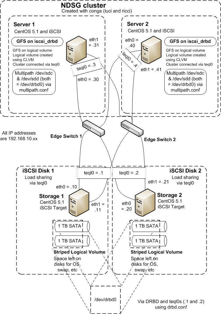
Unfortunately, once this configuration was complete we became aware that mdadm is NOT cluster aware! We decided to change the architecture to use DRBD and multipath.Reconfiguring with DRBD and Multipath
Both Distributed Replicated Block Device (DRBD) and Red Hat Cluster Suite (RHCS) use a single IP address to identify systems that are part of the distributed replicated block device (DRBD) or cluster (RHCS). In order to make the mirrored block device and the cluster for core-edge storage system reliable, we want to make sure they do not "break" if the link (or NIC) that DRBD or RHCS use fail. To do this we create a new load-shared "link" with a new IP address using Linux Advanced Routing and Traffic Control (LARTC).Using LARTC to create a load-shared IP address
On all the machines we want to create this single (load shared) IP address. To do this:modprobe sch_teql tc qdisc add dev eth0 root teql0 tc qdisc add dev eth1 root teql0 ip link set dev teql0In our network we have already set the IP addresses as shown below, so only the new IP address needs to be set. On Storage 1 we do this:
ip addr add dev teql0 192.168.10.1/24
Using DRBD to mirror the disk
First, ensure that DRBD is installed on both storage servers (I used yum in CentOS). Then create/etc/drbd.conf:
common {
    protocol C;
}
resource r0 {
    device /dev/drbd0;
    meta-disk internal;
    on storage1.ndsg.net.nz {
        disk /dev/VolGroup00/iscsidisk1;
        address 192.168.10.1:7799;
    }
    on storage2.ndsg.net.nz {
        disk /dev/VolGroup00/iscsidisk2;
        address 192.168.10.2:7799;
    }
}
You may have to "zero" enough space on your device:
dd if=/dev/zero bs=1M count=128 of=/dev/VolGroup00/iscsidisk1; syncThis creates space for the 128MB meta data disk. Now create the drbd device on the server.
drbdadm create-md _resource_drbdadm attach _resource_drbdadm connect _resource_>br>
cat /proc/drbd
See https://www.drbd.org/docs/install/ for more details.
Repeat this process on the other server.
On one of the storage servers synchronize the data (I am assuming both servers are currently empty):
drbdadm -- --overwrite-data-of-peer primary ~~resource~~Now enable a Primary/Primary configuration by adding:
resource ~~resource~~
  net {
    allow-two-primaries;
  }
  startup {
    become-primary-on both;
  }
  ...
}
to /etc/drbd.conf and using the following commands:
drbdadm adjust ~~resource~~
drbdadm primary ~~resource~~
For any problems please consult https://www.drbd.org/.
Use iSCSI to present the DRBD device
Now use iSCSI as specified above with two VERY IMPORTANT differences. This time you will be pointing to a single iSCSI target using two different IP addresses. We will also use a serial number to emulatedrbd0 being the same disk. Create a single ietd.conf file as before, add ScsiId=DRBD0 to the end of the Lun line in ietd.conf:
Lun 0 Path=/dev/drbd0,Type=fileio,ScsiId=DRBD0
and finally copy this file to the other storage server. This should "fool" the iSCSI initiators into thinking /dev/drbd0 is a single device (which for all intents and purposes it is!).
Use Multipath to specify a single device
Usescsi_id -g -u -s /block/sdc scsi_id -g -u -s /block/sddto make sure your iSCSI target is showing up as the same device on each connection (via the two TEQL devices, i.e., 4 NICs). Now edit
multipath.conf so that these scsi device (sdc and sdd) are seen as the same device with multiple paths:
# This is a basic configuration file with some examples, for device mapper
# multipath.
# For a complete list of the default configuration values, see
# /usr/share/doc/device-mapper-multipath-0.4.7/multipath.conf.defaults
# For a list of configuration options with descriptions, see
# /usr/share/doc/device-mapper-multipath-0.4.7/multipath.conf.annotated


# Blacklist all devices by default. Remove this to enable multipathing
# on the default devices.
#blacklist {
#        devnode "*"
#}
blacklist {
   devnode "^sda$"
        devnode "^sda[0-9]$"
   devnode "^sd[f-z]*$"
}

## By default, devices with vendor = "IBM" and product = "S/390.*" are
## blacklisted. To enable mulitpathing on these devies, uncomment the
## following lines.
#blacklist_exceptions {
#   device {
#      vendor   "IBM"
#      product   "S/390.*"
#   }
#}

## Use user friendly names, instead of using WWIDs as names.
defaults {
   user_friendly_names  yes
# Added from here
        multipath_tool       "/sbin/multipath -v0"
   udev_dir             /dev
        polling_interval     10
        selector             "round-robin 0"
        path_grouping_policy multibus
        getuid_callout          "/sbin/scsi_id -g -u -s /block/%n"
        prio_callout            /bin/true
        path_checker            readsector0
        rr_min_io               100
        max_fds                 8192
        rr_weight               priorities
        failback                immediate
}
##
## Here is an example of how to configure some standard options.
##
#
#defaults {
#   udev_dir      /dev
#   polling_interval    10
#   selector      "round-robin 0"
#   path_grouping_policy   multibus
#   getuid_callout      "/sbin/scsi_id -g -u -s /block/%n"
#   prio_callout      /bin/true
#   path_checker      readsector0
#   rr_min_io      100
#   max_fds         8192
#   rr_weight      priorities
#   failback      immediate
#   no_path_retry      fail
#   user_friendly_names   yes
#}
##
## The wwid line in the following blacklist section is shown as an example
## of how to blacklist devices by wwid.  The 2 devnode lines are the
## compiled in default blacklist. If you want to blacklist entire types
## of devices, such as all scsi devices, you should use a devnode line.
## However, if you want to blacklist specific devices, you should use
## a wwid line.  Since there is no guarantee that a specific device will
## not change names on reboot (from /dev/sda to /dev/sdb for example)
## devnode lines are not recommended for blacklisting specific devices.
##
#blacklist {
#       wwid 26353900f02796769
#   devnode "^(ram|raw|loop|fd|md|dm-|sr|scd|st)[0-9]*"
#   devnode "^hd[a-z]"
#}
multipaths {
       multipath {
               wwid                    ~~your scsi id goes here~~
               alias                   iscsi
               path_grouping_policy    multibus
               path_checker            readsector0
               path_selector           "round-robin 0"
               failback                immediate
       }
}
#multipaths {
#   multipath {
#      wwid         3600508b4000156d700012000000b0000
#      alias         yellow
#      path_grouping_policy   multibus
#      path_checker      readsector0
#      path_selector      "round-robin 0"
#      failback      manual
#      rr_weight      priorities
#      no_path_retry      5
#   }
#   multipath {
#      wwid         1DEC_____321816758474
#      alias         red
#   }
#}
#devices {
#   device {
#      vendor         "COMPAQ  "
#      product         "HSV110 (C)COMPAQ"
#      path_grouping_policy   multibus
#      getuid_callout          "/sbin/scsi_id -g -u -s /block/%n"
#      path_checker      readsector0
#      path_selector      "round-robin 0"
#      hardware_handler   "0"
#      failback      15
#      rr_weight      priorities
#      no_path_retry      queue
#   }
#   device {
#      vendor         "COMPAQ  "
#      product         "MSA1000         "
#      path_grouping_policy   multibus
#   }
#}
Set up GFS on RHCS
Now we have single mirrored disk presented to both Server 1 and Server 2 so we can create a cluster and GFS as above. However, one important difference is the presence of the TEQL devices. Use these IP addresses in the/etc/hosts file an d the cluster will not break if a single NIC goes down. Otherwise, use ricci and luci or cman, rgmanager and clvmd as before to set up a cluster with a GFS system.
Problem!
It appears that a TEQL device does not work well with RHCS, causing a split-brain problem in a 2-node cluster. We will replace the TEQL devices with bonded NICs since speed is not an issue in the controller cluster. First, replace/etc/sysconfig/network-scripts/ifcfg-eth0 and /etc/sysconfig/network-scripts/ifcfg-eth1 with the following file:
DEVICE=ethX # <- use eth0 or eth 1 as appropriate
USERCTL=no
ONBOOT=yes
MASTER=bond0
SLAVE=yes
BOOTPROTO=none
Then, create a new file
/etc/sysconfig/network-scripts/ifcfg-bond0:
DEVICE=bond0
IPADDR=192.168.10.4
NETMASK=255.255.255.0
NETWORK=192.168.10.0
BROADCAST=192.168.10.255
ONBOOT=yes
BOOTPROTO=none
USERCTL=no
Next, add the following lines to
/etc/modprobe.conf:
alias bond0 bonding
options bond0 mode=0 # <-mode=0 means balance-rr or balanced round robin routing
Finally, restart the networking
service network restartalternatively
/etc/rc.d/init.d/network restartNow, there should be a bonded dual-NIC interface for running RHCS.
More Architecture Problems
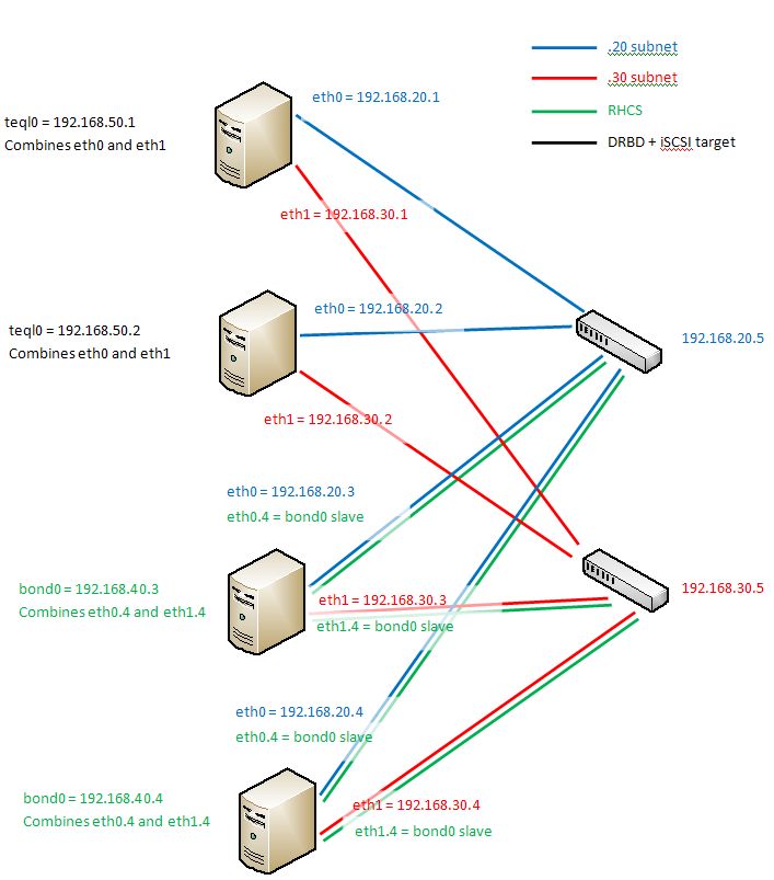
It appears that having the entire architecture on the same subnet means that only one switch can be "seen" at a time. Splitting it up using VLANs is not a solution as VLANs and TEQL devices don't seem to mix properly. By changing all eth0 to be on the 192.168.20.xx subnet and all eth1 to be on 192.168.30.xx subnet, we can see both switches (192.168.20.5 and 192.168.30.5 respectively). The TEQL devices can be 192.168.50.xx combining the 192.168.20.xx and 192.168.30.xx interfaces. The 192.168.50.xx subnet is then used for both iSCSI and DRBD. Finally, the bonding can happen on VLAN 4 (so add eth0.4 and eth1.4 to the two cluster servers) to provide redundancy for RHCS (see/etc/hosts).
The final architecture is shown below:
 -- MichaelOSullivan - 15 Dec 2010
 Topic revision: r7 - 2012-01-15 - TWikiAdminUser

Ideas, requests, problems regarding TWiki? Send feedback