OPNET Simulation Project: Summer Internship 2006/2007
Project Description
In a previous project Evaluation of Core-Edge Storage Area Network Designs using Simulation we investigated the suitability of Rockwell's Arena simulation package for simulating computer networks. In this project we trialled OPNET's IT Guru and Modeler as a alternative software package for computer network simulation. This project was intended as an initial discovery phase for our ongoing Network Simulation research.Project Diary
This is (an edited version of) the project diary of Bill (Xinsheng) Qu, an Honours Year Engineering Science undergraduate student. Last edited by Mike O'Sullivan and Cameron Walker on Jun 14, 2007.Week 1
16 November 2006: My First Day
Today is the first day of my studentship. It is a reading day. I am reading a paper called Evaluation of Core-Edge Storage Area Network Designs using Simulation, written by Cameron G.Walker, Michael J. O'Sullivan and Mihiriyani Elangasinghe. In this paper, they used a commercial simulation package called Arena simulation package to simulate the Cecil network and compare the performance of a core-edge network design to the current network used by Cecil. Cecil is the learning content management system at The University of Auckland and they only consider the back-end of the Cecil network. Their paper showed that Arena is not a good tool for simulating this as it may take a day just to simulate several minutes of the network. My responsibility this summer is to learn another well-known simulation software package IT Guru from OPNET, use it to simulate a similar network, and analyse the performance of a core-edge design.17 November 2006
I am still reading the paper (see 16 November 2006). I have also got a picture of the Cecil network structure. This really helps me to better understand the paper.20 November 2006
I have been told that I can use an academic version of OPNET's IT Guru starting next week. Therefore, the rest of this week I will study the paper with the help from the network diagram (see 16 and 17 November 2006). This is really the first time I need to understand terms such as "Switch", "Servers" and "SAN". I will research those terminologies this week.Week 2
This week is gonna be an IT Guru week for me! I have got OPNET's IT Guru Academic Edition 9.1 today which means the actual project is really starting now. My objective for this and next week is to get familiar with the software and learn as much as possible. I will be continuously posting my learning onto the lovely wiki.27 November 2006: Project and Scenarios
All network models are built in IT Guru using a Project and Scenarios. Each Project is a collection of different Scenarios for a modeled network. Each new network always needs a new Project to be built and each Project must contain at least one Scenario. Each scenario represents a unique configuration with changes to one or more of the topology, protocols, applications and profiles, or traffic.28 November 2006: Workflow of Constructing a New Model
To create a new network, a Project needs to be created first. After that, create a basic Scenario and define the topology and traffic. The user could construct other Scenarios in the Project with their own configurations (i.e., topology, protocols, traffic, etc). The user then needs to choose which statistics and results will be reported then run the simulation for the configured time and conditions. After running the simulation, the user could analyse the results and make corresponding modifications to their Scenario(s).29 November 2006: Problems with Switches
After some practice with IT Guru, I have started the construction of the Cecil back-end network topology. Unfortunately, the palette of network switches does not include either the Cisco 3550-12T or the Cisco 3750G-24FS, both of which are required for Cecil back-end network. One possible way to overcome this limitation is to derive a new switch based on the current resources available in the IT Guru Academic Edition palette.30 November 2006: Device Creator
IT Guru provides users with a powerful tool called Device Creator to create user-defined devices if the desired type is not included in the standard palette of the software. Users need to specify the device configuration and then the device can be automatically created. Typically, the types of device that Device Creator can create include: Router, Bridge, Hub, Switch, Multi-homed Host, Vendor Device, LAN Model, Cloud, Firewall, and Multi-Service Device. Here is a screen shot of the device types available in Device Creator:1 December 2006: Switch Parameters
Up until now, I have understood the process of creating a new vendor device or deriving one based on the palette items. However, I have run into problems because I don't know any of the parameters of the switch attributes within OPNET's IT Guru. This is difficult. I have searched other links, e.g., the Cisco website, but there is no valuable information about switch parameters. Therefore, we need to consult a network engineer about finding these parameters. My superviser Dr. Michael O'Sullivan has contacted a network engineer Warwick Dixon from ITSS (Information Technology Systems and Services). We will have a meeting with him (Monday at 1pm) next week to discuss the problems we are facing now. Hopefully I can understand a "Switch" better by Monday.1 December 2006: Deriving New Models
IT Guru allows users to derive a new model based on a parent model's specification. First, the user needs to select and place an existing standard or vendor model on to the Project Editor, then right click the model and alter the attributes to obtain the desired device for use in the network simulation. Another way of obtaining a new device is by using Device Creator (see above).Applications and Profiles
Profile and Application definition nodes will always be added to created networks to generate traffic. The Application node defines the types of standard network applications available for use in the constructed topology. The user also creates new Profiles. In each new Profile, the user defines the Name, Start Time, Duration and Repeatability of the traffic. All the profiles which will be applied to the network topology need to be configured in the Profile configuration. After that, the user could apply those defined Profiles to any of the workstations of the network. Using Applications and Profiles a user can build a complex traffic patterns within a network without repeating too much of their work.Week 3
4 December 2006: Meeting
Today, we had a meeting with Warwick Dixon, a network engineer from ITSS. The main output from the meeting is that he suggested we simulate an easier network than the Cecil back-end network first. This is because the Cecil back-end network has changed dramatically from the network diagram we have (from 2 years ago). We all agreed to simulate the Engineering Science network first, which is easier to simulate than the Cecil back-end network, but has all the devices we want to gain experience simulating. If our simulation gets convincing results, we will then move on to simulate another, larger network. Mr. Mark Bradly will help us to further develop the Engineering Science network simulation.6 December 2006: My Opinion of OPNET
I have been going through two tutorials from OPNET's IT Guru Academic Edition 9.1. These tutorials are included in the Academic Edition, which helps users become familiar with the IT Guru software. The first tutorial is about the basics of using IT Guru, several common protocols and vendor devices are discussed. The Project Editor is the main area of modelling and simulation in IT Guru. In the Project Editor, we create the network model, collect statistics, execute simulations and analyze the results. In the Project Editor window, there are five sections:- Menu Bar
- Tool Button
- The Workspace
- The Message Area
- Tooltips
- Import a topology
- Create a network by placing nodes and links
- Use a Rapid Configuration
- OPNET Lab Manual
- OPNET Training Manual
- OPNET IT Guru: A Tool For Network Education
Week 4
11 December 2006
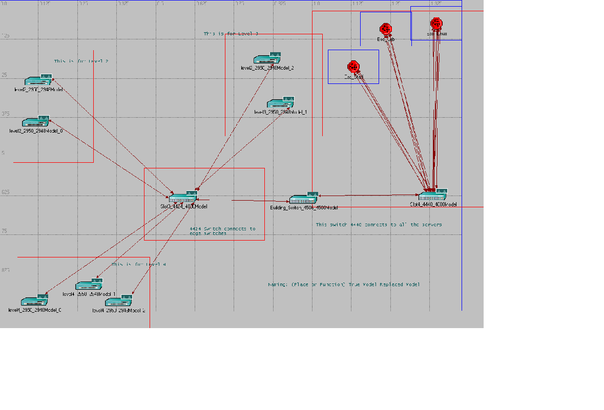
Today, I received the description of the Engineering Science network from Mark Bradley. The network looks simpler than then original Cecil back-end network, this is a good news.Project Introduction
We have decided to simulate Engineering Science departmental network. The Department of Engineering Science (DES) is located on the 2nd, 3rd and 4th floor of Uniservices House, 70 Symonds Street. Here is the description of the DES network on levels 2, 3, and 4. The information is provided by:- Mark Bradley (ITS staff)
- Rao Cherukuri (DES IT staff)
- Percy Barboza (DES IT staff)
Week 5
11 January 2007
Some Switch Information From the description of the network (see the Project Introduction) we know the building switch has two slots. Here is the information for the building switch and the associated slot cards:- Building Switch: Catalyst 2950T-48-SI 48 10/100 and 2 10/100/1000BASE-T ports
- Slot cards:
- WS-X4424-GB-RJ45: Catalyst 4000 24-port 10/100/1000 Module (RJ45)
- WS-X4448-GB-RJ45: Catalyst 4000 48-port 10/100/1000 Module (RJ45)
12 January 2007: Some Problems
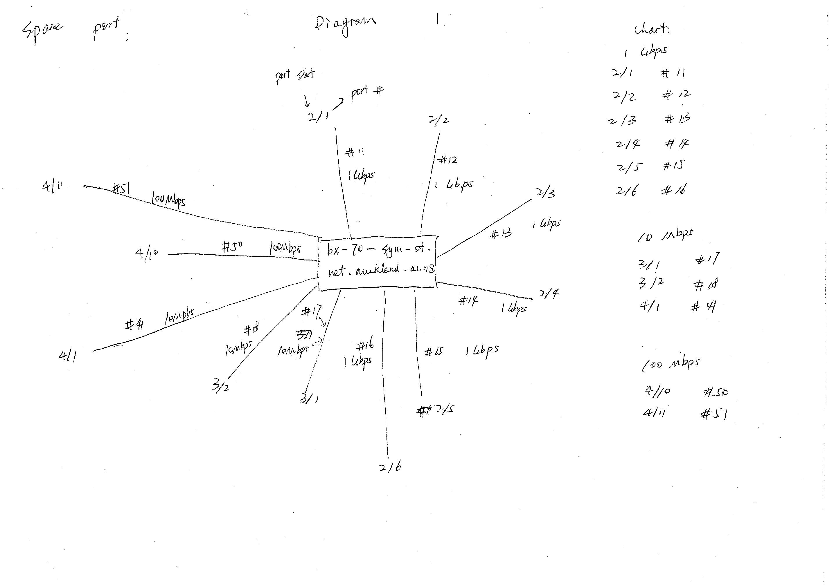
My superviser, Michael, is gonna be away next week. Before he left, he gave me some information from Multi Router Traffic Grapher (MRTG). MRTG is a tool to monitor the traffic load on network-links. From the information we extracted from MRTG, we can probably get some traffic information for our constructed network topology. From the information I have now, and because of the help I received from Rao and Percy, our dedicated IT staff, I can identify the appropriate devices for the Department of Engineering Science. But there are some things I can't figure out from MRTG's Information, e.g.- 2/1 -- 70-Sym-St-Bx-bx-sym-st.net.auckland.ac.nz_2_1 Max 1 Gbps
15 January 2007
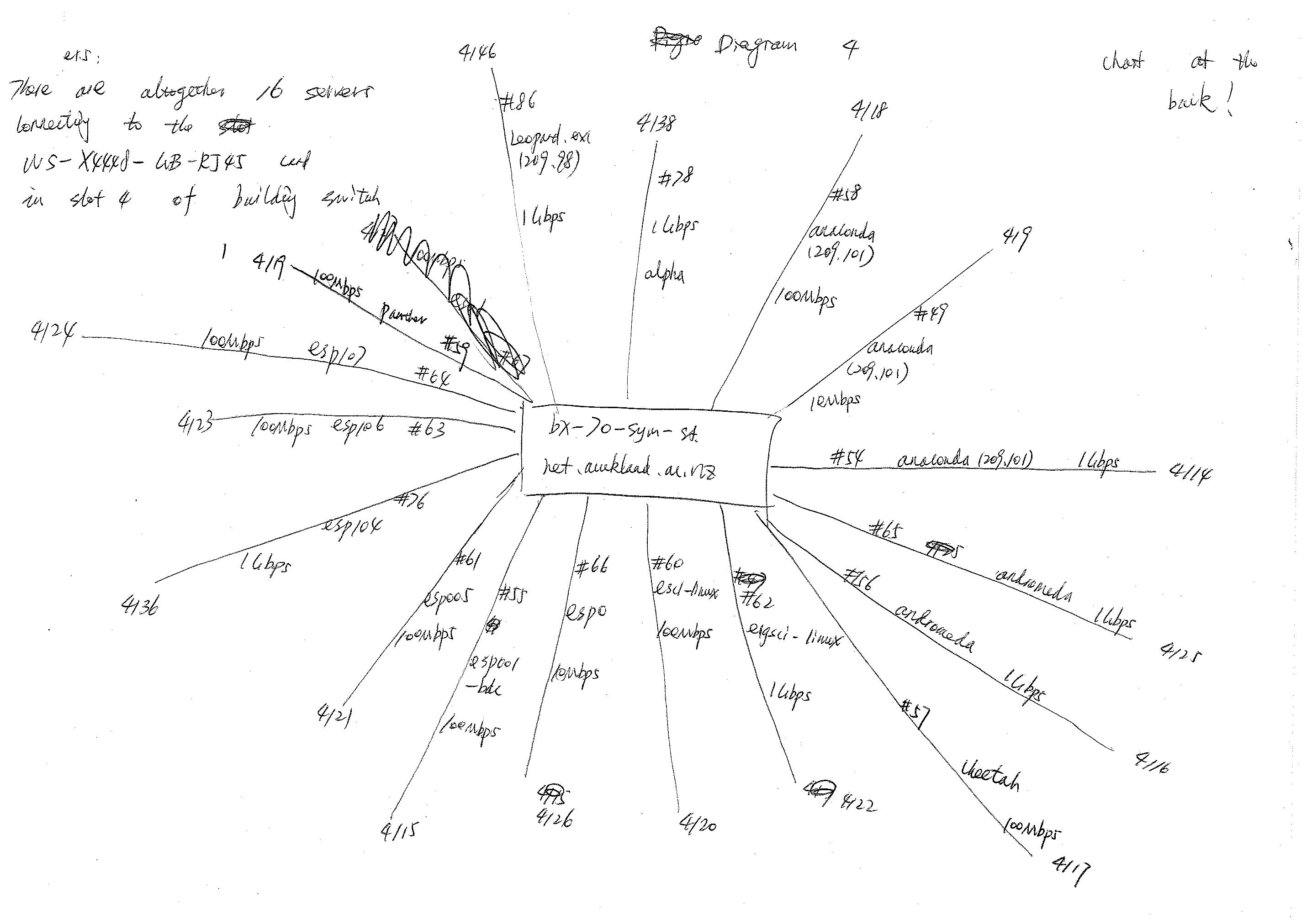
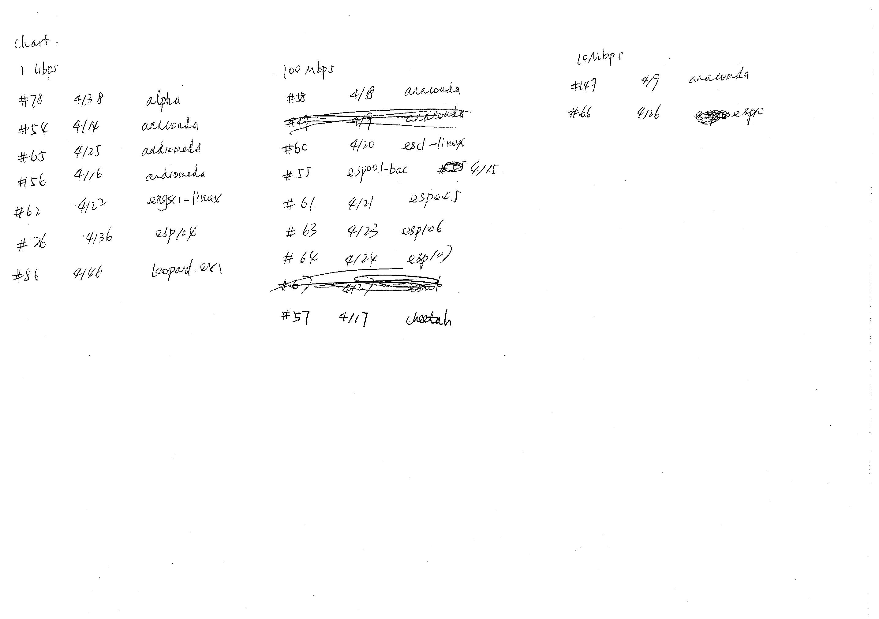
Today, I asked Rao and Percy some questions about MRTG (thanks for your time guys). I have got some useful information. The next thing I need to do is try to contact Mark Bradley, who knows some more information and I could learn more about MRTG and the network topology. Rao said all the servers for Engineering Science are located on Level 4, there are 16 altogether, 14 servers in the building and 2 outside. This matches with the information provided from MRTG. However, they can't identify the servers from the names listed on MRTG. They suggested it may be better to talk to Mark Bradley about this. However, I found from the previous email Mark wrote that it is better to contact Tiong Lim or Andrew Cantell regarding the server information. I am not sure if it is Ok to contact them straight away by myself. Anyway, the names are not important at this stage for constructing the topology. Rao also suggests that it is actually better to analyse the ports instead of servers because the servers are being updated but the ports are not. I don't understand this part at all. Apart from that, he said the Engineering Science servers are updating this month and information such as the speed and name of the servers may change (there will still be 16). Next week I need to ask them again about those servers. I have constructed the updated network topology on IT Guru. I still can't figure out how to model the slot cards on the building switch, there is not much help on the internet either. Another major problem is that the IT staff don't know anything about 2/1, 2/2, etc. They said it would definitely be better to ask Mark about this. Probably I will contact Mark sooner or later. I have sent an email to Michael and told him what has happened, he is away this week.16 January 2007
Rao told me today that the Engineering Science servers are still updating, so we need to wait until they finish and then get the new information from MRTG. I have got the email from my superviser Michael today, which means I have more work to do now. I am still learning from the information Michael gave me from MRTG. In the "Device Information" sheet, it appears "Max 1 Gbps" means the maximum speed of 1 Gbps (obvious?). However, this means that the 16 servers in the Department of Engineering Science each have a different connection to the edge switch. This is different to the information I obtained from Rao. I have sent a email to Mark asking about this. I am looking forward to his reply.17 January 2007: A Big, Big Mistake
What a big mistake I made! I just realised today that I treated a router as a switch for our project! The building switch for 70 Symonds Street is WS-4506. This switch is not available in OPNET's IT Guru Academic Edition, so I thought I could use a 4500 instead (for now). However, I forgot to read the "node description" for this switch. This is actually a Router! Routers in IT Guru have a lot more attributes than Switches. There are far less Switch attributes… How did I make such a stupid mistake!Week 6
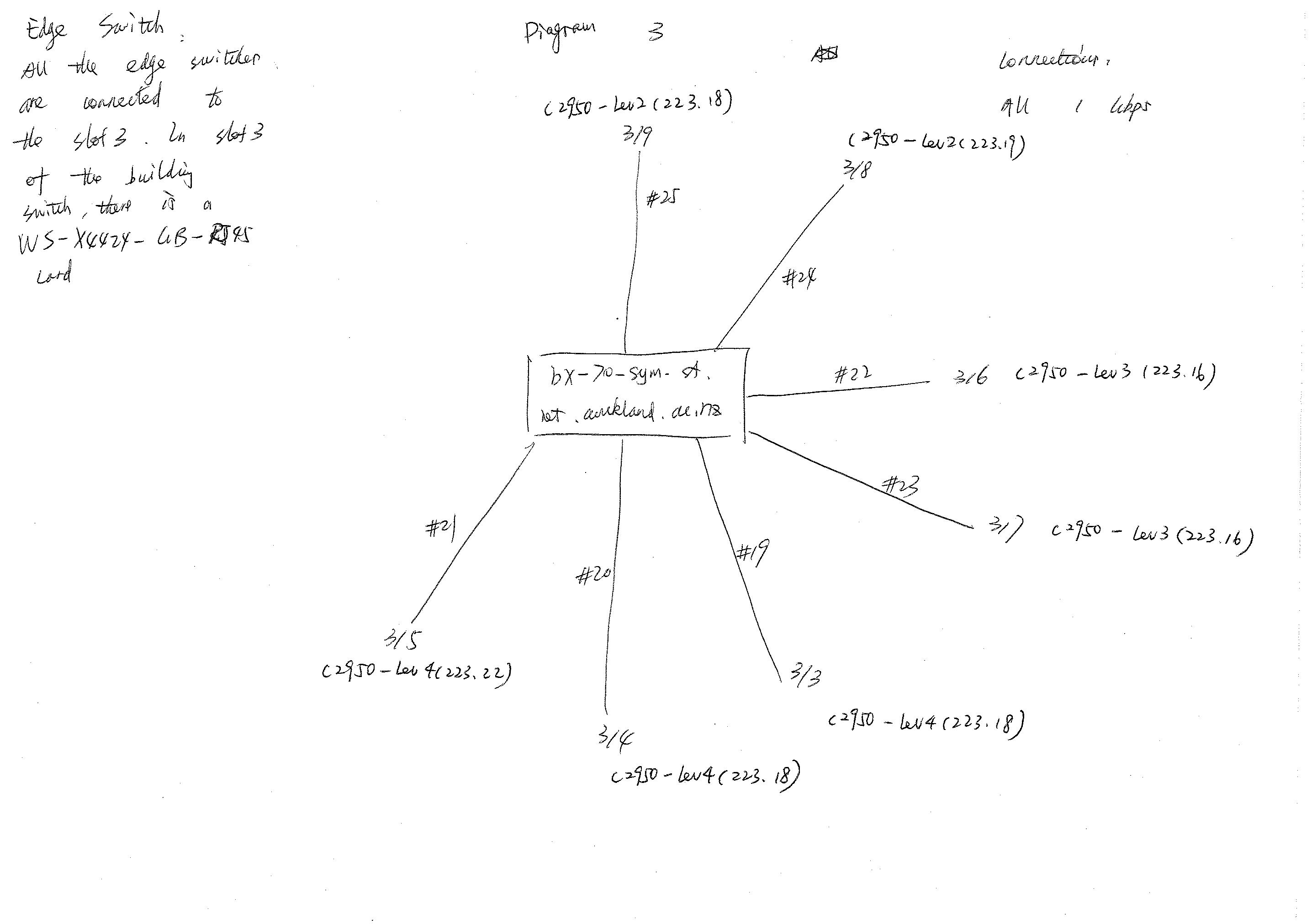
h3 22 January 2007 I got the updated version of OPNET Modeler 12.0. However, I have encountered difficulties with "License Management" in Modeler. The error is "You have either "Student" or "Standard" Extranet privileges to access the OPNET Website". Probably I need ask Rao for help. Mark emailed me about back the question I have asked, and I know 2/1 means the 2nd port of the 1st edge switch. Also, from tomorrow on, I need to work on the MRTG information to understand more about the edge switches, e.g., the number and location of the workstations connected to a specific edge switch. h3 23 January 2007 Today, Michael assigned some tasks to me for figuring out the edge switches. I need to identify specific edge switches from MRTG and their connections to different workstations. We are planned to finish constructing the topology within approximately 2 weeks. h3 More about MRTG I have spent the rest of the day trying to figure out information about the edge switches from MRTG. Here is a summary\: Level 2 * ex-439-fd212-1.net.auckland.ac.nz is the edge switch C2950-Lev2, there are 47 FastEthernet connections (are these to workstations?) + 1 wap-439-209 * ex-439-fd212-2.net.auckland.ac.nz is the edge switch C2950-Lev2, there are 48 FastEthernet connections (again, are these workstations) Level 3 * ex-439-fd312-1.net.auckland.ac.nz is the edge switch C2950-Lev3, there are 48 FastEthernet connections * ex-439-fd312-2.net.auckland.ac.nz is the edge switch C2950-Lev3, there are 47 FastEthernet connections + 1 wap-439-329a Level 4 * ex-439-fd412-1.net.auckland.ac.nz is the edge switch C2950-Lev4, there are 48 FastEthernet connections * ex-439-fd412-2.net.auckland.ac.nz is the edge switch C2950-Lev4, there are 48 FastEthernet connections * ex-439-fd412-3.net.auckland.ac.nz is the edge switch C2950-Lev4, there are 48 FastEthernet connections The connections to the building switch in MRTG must be GigabitEthernet0/1, because the maximum speed is 1 Gbps. I don't know what GigabitEthernet0/2 is, maybe it is irrelevant to our project. h3 24 January 2007 I got the updated OPNET Modeler 12.0 today and I was trying to get the license via Internet. Problems occurred when getting the license\: "Operation did not go through. The username, password and group ID yo entered are not authorized to access licenses for this group. Please make sure that you have entered the correct username and password for the group that you are working with. (error - 16148)" I emailed the problem to support@opnet.com and they replied saying that\: "students are not allowed to administer licenses. You will need to have your professor, or an administrator add these licenses for you." Probably I need to ask Michael tomorrow. h3 25 January 2007 Michael told me today that he needs to install the software on a server. I have to uninstall it on my own computer. Sajy, the computer system officer helped me for doing this. Michael is gonna be away until next Wednesday. During this time, I will play around with the latest version of OPNET Modeler 12.0. h3 26 January 2007 With the help from Sajy, the Computer Systems Officer in the Department of Engineering Science, I have installed OPNET Modeler 12.0 successfully. It is pretty much the same as the IT Guru Academic Edition 9.1. From next week on, my new task is gonna be constructing the topology using this new edition. {link:Return to Contents|#contents} h2 {anchor:|week7}{anchor}Week 7 h3 29 January 2007 Michael will be back this Wednesday, so I was playing with Modeler 12.0 the whole day. The good news about Modeler 12.0 is that it has a Help section and there are more and better tutorials than in IT Guru 9.1. I sent an email to support@opnet.com to ask about the difficulty I have on modeling the slots of the building switch. The reply said that I have to create the custom device for each slot. The {link:Cisco Website|https://www.cisco.com/en/US/products/hw/switches/ps663/products_configuration_guide_chapter09186a00801762ec}- Updated_EngSci.bmp: Updated_EngSci.bmp


| I | Attachment | History | Action | Size | Date | Who | Comment |
|---|---|---|---|---|---|---|---|
| |
Building_Switch_Spares_1.jpg | r1 | manage | 242.3 K | 2010-12-16 - 04:32 | MichaelOSullivan | |
| |
Building_Switch_Spares_2.jpg | r1 | manage | 276.7 K | 2010-12-16 - 04:33 | MichaelOSullivan | |
| |
Building_Switch_to_Edges.jpg | r1 | manage | 243.6 K | 2010-12-16 - 04:33 | MichaelOSullivan | |
| |
Building_Switch_to_Servers_1.jpg | r1 | manage | 393.1 K | 2010-12-16 - 04:33 | MichaelOSullivan | |
| |
Building_Switch_to_Servers_2.jpg | r1 | manage | 233.9 K | 2010-12-16 - 04:33 | MichaelOSullivan | |
| |
Cecil_Network_Mid.bmp | r1 | manage | 2769.1 K | 2010-12-16 - 04:31 | MichaelOSullivan |
Topic revision: r4 - 2012-01-15 - TWikiAdminUser

Ideas, requests, problems regarding TWiki? Send feedback